Retrofit mechanism
I designed this prototype to operate an existing wall switch mechanically, without changing the building wiring. The CAD model uses a lead screw and guided carriage to move the actuator across the switch. That layout lets me work out the travel, mounting clearance, and alignment before building the housing.
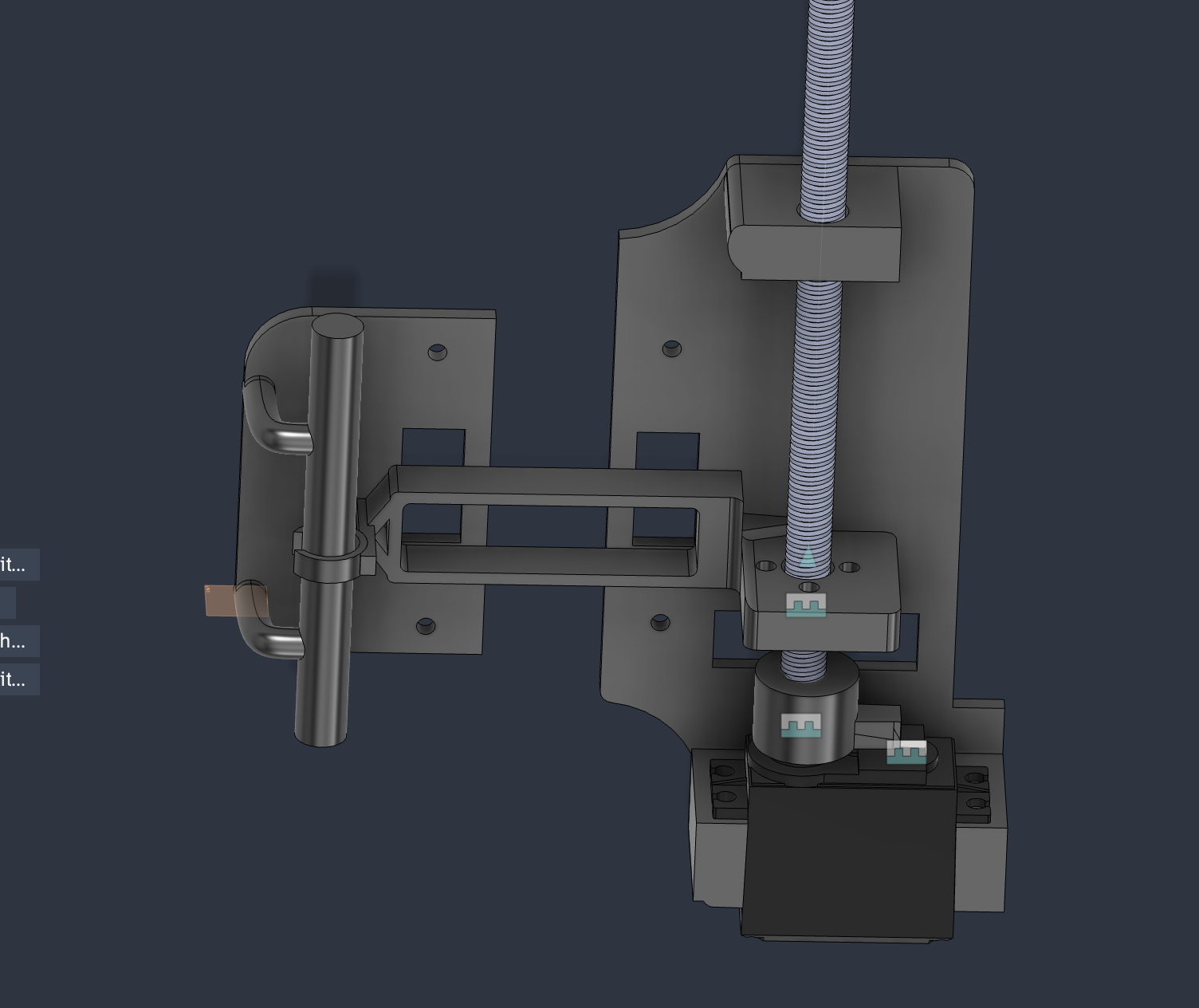
Control prototype
The wall-mounted prototype places the actuator beside the switch. An ESP32 board and push button are wired on a breadboard for control testing; the wiring is still exposed at this stage. The photo documents the physical arrangement and test setup, rather than a finished enclosure or a verified phone, voice, or scheduling feature.
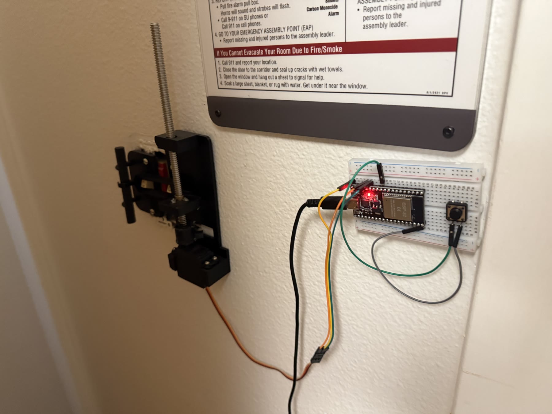
The next mechanical checks are repeatable switch travel, end-stop behavior, and mounting stiffness. Those tests matter because the actuator has to move the switch reliably without loading the switch beyond normal travel.